
TP-15 Connector Compatibility with Electronic Projects: Guide for Makers in South Africa
Learn how to assess TP-15 connector compatibility: pinouts, pitch, current ratings, wiring diagrams, and South African buying notes including stock and accessories.
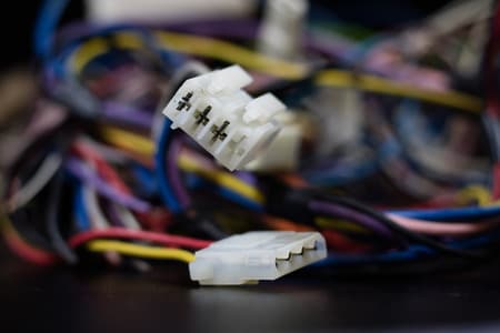
Verify Pinout First
Always confirm pin numbering and orientation from datasheets or photos.
Match Current Ratings
Ensure pin and trace ratings meet summed current; parallel pins if safe.
Use Proper Tools
Crimp tools, strain relief, and continuity checks prevent failures.
Overview: What is a TP-15 Connector?
The TP-15 connector (often used for small signal and power connections) is a compact multi-pin header/plug format encountered on sensor modules, legacy equipment, and custom cables. This guide explains TP-15 connector compatibility with electronic projects, focusing on pin mapping, current/voltage considerations, wiring conventions, and practical checks you should do before integrating one into a design.
Common use-cases
- Interfacing sensor modules and small motor drivers in robotics and prototyping.
- Custom cable harnesses between PCBs and control panels.
- Replacement or repair on consumer electronics and education kits.
Why compatibility matters
Mismatched TP-15 wiring or assumptions about pin order can lead to signal inversion, short circuits, or damaged devices. South African makers and students should confirm pinouts, check current ratings in ZAR-priced components if upgrading power circuits, and verify branch stock or lead times for correct mating plugs and crimp terminals.
Standards, Pinouts and Physical Specs
TP-15 is a descriptor used in many hobby/legacy contexts rather than a single international standard. Always refer to the module or product datasheet for exact mechanical dimensions, pin numbering, and keyed features. Below is a typical physical and electrical checklist you should compare to a product page or datasheet.
| Parameter | Typical Value / Range | Notes |
|---|---|---|
| Pin count | 15 pins | Verify keyed orientation on plug/housing |
| Pitch | 2.54 mm (typical) or 2.00 mm (less common) | Measure with calipers or check datasheet |
| Current per pin | 0.5 A to 5 A depending on contact size | High-current pins may require larger contacts |
| Voltage rating | Typically up to 50 VDC for small connectors | Confirm for mains or high-voltage circuits |
Practical check: If you order TP-15 mating plugs from buy-pcb-connectors-tp-15-online, check the product page for pitch and make a note of the stock level at the Samrand or Cape Town branch to avoid delivery delays.
Typical pin numbering/diagram (example)
Top view of female PCB header (pins numbered left-to-right)
[ 1 ][ 2 ][ 3 ] ... [15]
When mating, ensure key/notch aligns so pin 1 on plug matches pin 1 on board.
Always capture a photo and document the pin numbering when you first encounter a TP-15 connector - many compatibility issues start from ambiguous pin orientation. For guidance on installing and documenting connectors, see best-practices-for-pcb-connector-installation.
Related Connectors, Wire & Cable Products
Discover quality connectors, wire & cable products related to TP-15 Connector Compatibility with Electronic Projects: Guide for Makers in South Africa

2.54mm Pcb Socket Connector Double Rows Straight Pins Solder Tail
2.54mm Pcb Socket Connector Double Rows Straight Pins Solder Tail

Dil Ic Socket Tin/gold Flash 32p (12) Rohs
Dil Ic Socket Tin/gold Flash 32p (12) Rohs

Dil Ic Socket Tin/gold Flash 40p (10) Rohs
Dil Ic Socket Tin/gold Flash 40p (10) Rohs

Dil Ic Socket Tin/gold Flash 28p (14) Rohs
Dil Ic Socket Tin/gold Flash 28p (14) Rohs

Dil Ic Socket Tin/gold Flash 28p (17) Rohs.
Dil Ic Socket Tin/gold Flash 28p (17) Rohs.

Dil Ic Socket Tin/gold Flash-nrw28p(14) Roh
Dil Ic Socket Tin/gold Flash-nrw28p(14) Roh

Dil Ic Socket Tin/gold Flash-st248p(17) Rohs
Dil Ic Socket Tin/gold Flash-st248p(17) Rohs

Dil Ic Socket Tin/gold Flash-std20p(20) Roh
Dil Ic Socket Tin/gold Flash-std20p(20) Roh

Dil Ic Socket Tin/gold Flash-std18p (22) Rohs
Dil Ic Socket Tin/gold Flash-std18p (22) Rohs

Dil Ic Socket Tin/gold Flash-std16p(25) Ro
Dil Ic Socket Tin/gold Flash-std16p(25) Ro

Dil Ic Socket Tin/gold Flash-std14p(29) Roh
Dil Ic Socket Tin/gold Flash-std14p(29) Roh

Dil Ic Socket Tin/gold Flsh-std6p(69) Rohs
Dil Ic Socket Tin/gold Flsh-std6p(69) Rohs
Selection Criteria: Matching TP-15 to Your Project
Electrical considerations
- Sum currents on adjacent pins and avoid using low-current contacts for power rails.
- Calculate power dissipation using P = V * I for each pin; derate contacts if ambient temperature is high.
- For mixed-signal use, separate power and sensitive analog signals where possible to reduce noise coupling.
Mechanical and assembly considerations
Choose housings with strain relief and keyed polarisation. If crimping cables, use the correct crimp die and verify contact retention force. For student labs, consider pre-assembled jumper harnesses to reduce assembly errors.
Wiring Examples, Calculations and Troubleshooting
Example: Supplying a 5V logic board via TP-15
Suppose your board needs 5V at 1.2 A and multiple sensors draw an additional 0.8 A total. Total current on the 5V pin: I_total = 1.2 A + 0.8 A = 2.0 A. If the TP-15 contact is rated at 1 A, you should either use two adjacent pins in parallel (if allowed by the device) or select a connector with higher per-pin current rating.
Parallel pin current calculation: with two pins in parallel, each would carry ~1.0 A. Check that the plug and PCB trace widths support the split current; use Ohm's law to estimate voltage drop: V_drop = I * R_contact. Small contact resistances (tens of milliohms) can still cause millivolt drops multiplied by high currents.
Wiring diagram (ASCII) for a 5V and GND pair plus 3 signal lines
TP-15 Plug (front view)
[ P1:5V ] [ P2:GND ] [ P3:SIG1 ] [ P4:SIG2 ] [ P5:SIG3 ] ... [ P15 ]
Use thicker wire (e.g., 22 AWG / ~0.33 mm^2) for power pins, and 26-28 AWG for signals.
Troubleshooting checklist
- Measure continuity pin-to-pin before powering the system.
- Check for reversed polarity by measuring voltage between the expected power pins with a multimeter.
- If contact heating occurs, reduce current or select a connector with higher current rating; heating indicates excessive contact resistance or poor mating.
- Confirm that mating connectors are the same pitch and keyed orientation to avoid bent pins or shorts.
Local Practical Notes for South African Makers
Communica stocks a wide range of connectors, housings, and crimp terminals suitable for TP-style connector work. When planning purchases, factor in lead times (some niche housings may be special order), branch pickup options (Samrand, Pretoria CBD, Cape Town), and VAT invoices for education or procurement use. For a small project budget example: typical crimp terminal packs or a 15-pin housing may cost between ZAR 30 and ZAR 300 depending on brand and quality (estimates only; check current prices on product pages).
Recommended accessories
- Proper crimp tool matched to the contact series.
- Heatshrink tubing and strain-relief clamps for cable bundles.
- Multimeter and continuity tester for verification before powering up.
When to Replace vs Adapt
If pin current demands, pitch, or mechanical robustness are inadequate for your application, prefer replacing the connector with a higher-rated compatible series or redesigning the cable harness to use separate power terminals. For one-off repairs, adapter cables that remap TP-15 pins to screw terminals can be a practical interim solution.
Sources
Communica supplies semiconductors and electronic components to industries such as automotive, electrical, automation, mining, and education.
Disclaimer: This content is for educational purposes only. Product availability, pricing, and specifications are subject to change. Always verify current details on the retailer's website before making a purchase. We may earn affiliate commissions from qualifying purchases.


Frequently Asked Questions
Get answers to common questions about Connectors Wire And Cable
Why Choose Communica?
*Free Shipping
Free shipping for orders over ZAR 1,000.00.
7-Day Returns
Get a full refund if you had the product for less than 7 days.
Quick Delivery
Nationwide delivery within 2 - 4 working days.
