
CQ211C MOD Fuse Installation Guide - Safe Replacement & Wiring (South Africa)
Step-by-step CQ211C MOD fuse installation guide for South African makers and technicians: selection, safe removal, wiring, testing and local stock notes.
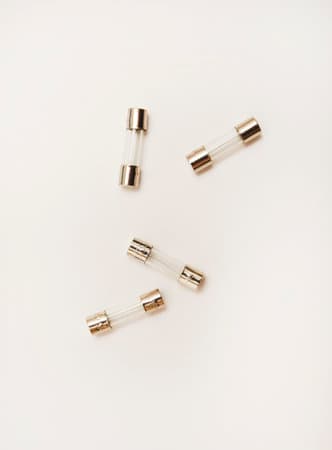
Match Key Ratings
Ensure current, voltage and time-characteristic match the original CQ211C MOD fuse.
Safe Removal & Test
Isolate, verify zero voltage, replace, then continuity and inrush checks.
Local Stock & Records
Check Communica branches for spares, keep VAT invoices and installation logs.
Overview: What is the CQ211C MOD Fuse and When to Replace It
The CQ211C MOD fuse (referred to here as CQ211C MOD fuse) is a modular protective element used in panel and equipment protection schemes. This guide covers selecting the correct replacement CQ211C MOD fuse, basic electrical checks, safe removal and installation, and post-installation testing. Whether you are a student, maker, technician or procurement professional in South Africa, these steps will help you minimise downtime and ensure a safe install.
Safety First
Before starting any fuse work, isolate the circuit at the upstream breaker or mains switch and verify zero voltage with a suitable multimeter or voltage tester. Use insulated tools and personal protective equipment (insulated gloves, safety glasses). If you are unfamiliar with live electrical work, consult a qualified electrician.
Identify the Correct CQ211C MOD Fuse: Specs & Markings
Replacement accuracy depends on matching the fuse's key parameters: rated current (A), breaking capacity (kA or A), voltage rating (V), and time characteristic (fast-blow, slow-blow / time-delay). Inspect the existing fuse for printed markings; typical markings include model (CQ211C MOD or variant), current rating (e.g., 10A), voltage (e.g., 250V), and a breaking capacity code.
| Parameter | Typical Marking / Example | Why it matters |
|---|---|---|
| Rated current | 10A | Ensures fuse opens at expected load to protect wiring and loads. |
| Rated voltage | 250VAC | Must be >= system voltage to clear faults safely. |
| Time characteristic | gG (general purpose) or aM | Affects tolerance to inrush currents (motors, transformers). |
Local stock and equivalent parts
Communica stocks a wide range of fuses and holders across its Samrand, Pretoria and Cape Town branches. If CQ211C MOD exact part is not listed, match rated current, voltage and time characteristic. For procurement teams, request VAT invoices and lead-time estimates when ordering replacements. Typical retail ZAR price ranges for modular fuses are R50-R400 per unit depending on rating and brand; prices are estimates and subject to stock and supplier variations.
Tools & Test Equipment Needed
- Insulated screwdriver set
- Voltage tester and digital multimeter (DMM)
- Fuse puller (if provided) or insulated pliers
- Replacement CQ211C MOD fuse and appropriate fuse holder
- Label printer or marker for circuit tagging
Pre-removal checklist
- Confirm circuit is isolated and locked-out where required.
- Discharge any stored energy in capacitors (e.g., motor drives) per manufacturer instructions.
- Photograph the fuse wiring to record polarity and connections.
Related Circuit Protection & Passive Components Products
Discover quality circuit protection & passive components products related to CQ211C MOD Fuse Installation Guide - Safe Replacement & Wiring (South Africa)

8a Cer 6x32 S/b | Ceramic Fuse • Slow Blow • 8a • 6ø X 32mm
8a Cer 6x32 S/b | Ceramic Fuse • Slow Blow • 8a • 6ø X 32mm

8a Cer 6x32 F/b | Ceramic Fuse • Fast Blow • 8a • 6ø X 32mm
8a Cer 6x32 F/b | Ceramic Fuse • Fast Blow • 8a • 6ø X 32mm

8a Cer 5x20 S/b | Ceramic Fuse • Slow Blow • 8a • 5ø X 20mm
8a Cer 5x20 S/b | Ceramic Fuse • Slow Blow • 8a • 5ø X 20mm

8a Cer 5x20 F/b | Ceramic Fuse • Fast Blow • 8a • 5ø X 20mm
8a Cer 5x20 F/b | Ceramic Fuse • Fast Blow • 8a • 5ø X 20mm

8a 6x32 S/b | Glass Fuse • Slow Blow • 8a • 6.3Ø X 32mm
8a 6x32 S/b | Glass Fuse • Slow Blow • 8a • 6.3Ø X 32mm

8a 6x32 F/b | Glass Fuse • Fast Acting • 8a • 6.3Ø X 32mm
8a 6x32 F/b | Glass Fuse • Fast Acting • 8a • 6.3Ø X 32mm

8a 5x20 S/b | Glass Fuse • Slow Blow • 8a • 5Ø X 20mm
8a 5x20 S/b | Glass Fuse • Slow Blow • 8a • 5Ø X 20mm

8a 5x20 F/b | Glass Fuse • Fast Acting • 8a • 5Ø X 20mm
8a 5x20 F/b | Glass Fuse • Fast Acting • 8a • 5Ø X 20mm

80ma 6x32 S/b | Glass Fuse • Slow Blow • 80ma • 6.3Ø X 32mm
80ma 6x32 S/b | Glass Fuse • Slow Blow • 80ma • 6.3Ø X 32mm

80ma 6x32 F/b | Glass Fuse • Fast Acting • 80ma • 6.3Ø X 32mm
80ma 6x32 F/b | Glass Fuse • Fast Acting • 80ma • 6.3Ø X 32mm

80ma 5x20 S/b | Glass Fuse • Slow Blow • 80ma • 5Ø X 20mm
80ma 5x20 S/b | Glass Fuse • Slow Blow • 80ma • 5Ø X 20mm

80ma 5x20 F/b | Glass Fuse • Fast Acting • 80ma • 5Ø X 20mm
80ma 5x20 F/b | Glass Fuse • Fast Acting • 80ma • 5Ø X 20mm
Step-by-Step Removal and Installation
1. Verify isolation
Use a voltage tester across the fuse terminals and between terminals and earth to confirm there is no mains present. Lock-out / tag-out procedures are recommended for industrial installs.
2. Remove the failed CQ211C MOD fuse
Open the panel cover and, using insulated tools, remove the fuse module from its holder. Use a fuse puller for tight fits. Inspect the holder and terminal screws for heat damage or corrosion; replace the holder if signs of arcing or overheating are present.
3. Install the replacement
Fit the new CQ211C MOD fuse of matching ratings into the holder. Tighten terminal screws to the torque recommended by the equipment or terminal manufacturer; hand-tight can loosen under vibration. Reinstall any retained clips or covers.
4. Post-installation tests
Before re-energising, perform a continuity check across the fuse (DMM continuity or low-ohms). After power-up, monitor inrush and running current with a clamp meter to confirm the replacement is not undersized. Example formula for expected running power: P = V x I. For a 230VAC circuit with a 5A load, P = 230 x 5 = 1,150 W.
Troubleshooting & Common Issues
Fuse keeps blowing immediately
Immediate re-blow suggests a short circuit or wiring fault downstream. Isolate loads and test sections individually. Use the DMM to measure resistance between live and neutral, and live/neutral to earth; near-zero resistance indicates a short.
Intermittent blow on motor start
If the CQ211C MOD fuse blows only on start, consider time-delay (slow-blow) fuse types or check motor inrush specs. Verify the motor and starter circuit, and ensure correct fuse time-characteristic is chosen to handle inrush without compromising protection.
Overheating at fuse holder
Loose terminals and corrosion increase contact resistance, producing heat. Torque screws to spec, clean contacts, and replace damaged holders. In South African environments, coastal corrosion can accelerate contact degradation; consider stainless or corrosion-resistant hardware in those installations.
Practical Examples and Calculations
Example: Selecting a fuse for a 230VAC heating element drawing 8A continuous with 25% start headroom. Recommended fuse = 8A x 1.25 = 10A. Choose a CQ211C MOD fuse rated 10A, 250VAC with appropriate time characteristic if inrush is expected.
Wiring diagram (single-phase, simplified):

   L -----[ Fuse (CQ211C MOD) ]-----+----- Load
                                     |
                                     +----- Earth
   N -------------------------------+----- Load return
Documentation & Record Keeping
Record the replacement date, part number, rated current, and test readings (pre- and post-installation) in the equipment log. For procurement, keep the supplier invoice (VAT inclusive) and note lead time for future spares planning.
Local note: check Communica's product index under Circuit Protection & Passive Components and Branches & Trading Hours to confirm local stock and pickup options at Samrand, Pretoria or Cape Town. Delivery lead times vary; for critical spares, maintain an on-site spare stock (one to three units depending on downtime cost). For local sourcing details, see where to buy CQ211C MOD fuses in South Africa.
Sources
Communica supplies semiconductors and electronic components to industries such as automotive, electrical, automation, mining, and education.
Disclaimer: This content is for educational purposes only. Product availability, pricing, and specifications are subject to change. Always verify current details on the retailer's website before making a purchase. We may earn affiliate commissions from qualifying purchases.


Frequently Asked Questions
Get answers to common questions about Circuit Protection And Passive Components
Why Choose Communica?
*Free Shipping
Free shipping for orders over ZAR 1,000.00.
7-Day Returns
Get a full refund if you had the product for less than 7 days.
Quick Delivery
Nationwide delivery within 2 - 4 working days.
