
Best Practices for Using GDM2009 GY Connectors in Projects and Assemblies
A practical guide to using GDM2009 GY connectors: wiring, footprint, crimping, testing and local South African sourcing tips for makers and engineers.
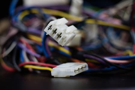
Check Datasheet First
Confirm pinout, rated current, and recommended wire/crimp before assembly.
Crimp & Strain Relief
Use the correct dies, ferrules, and cable clamps to avoid failures.
Local Stock & Traceability
Keep spares, note lead times, and request VAT invoices for institutional orders.
Overview: What the GDM2009 GY Connector Is and Where It Fits
The term GDM2009 GY connector typically refers to a compact multi-pin board-to-cable connector used in consumer electronics, industrial controllers, and maker projects. This guide covers best-practices for mechanical mounting, contact preparation, electrical sizing, and common assembly workflows. Whether you are a university lab, maker, technician, or procurement team in South Africa, these recommendations help reduce failures, simplify installation, and speed up commissioning.
Why follow connector best practices?
Connectors are small points of failure in any system: poor crimps, wrong wire gauge, incorrect mating force, or inadequate strain relief cause intermittent signals, heating, or connector damage. Adopting consistent practices reduces rework, shortens lead times, and supports repeatable builds for prototypes and production runs.
Key Specifications & Handling Considerations
Before assembly, review the GDM2009 GY datasheet for pin count, mating orientation, mechanical retention, and recommended wire/crimp types. If the exact datasheet is not available, treat these items as the primary checklist to verify.
| Parameter | Typical Guidance | SA Practical Notes |
|---|---|---|
| Contact type | Receptacle/pin; plated contact (e.g., tin or gold) | Confirm plating for low-voltage signals; gold for low-current/low-voltage is preferable when available. |
| Rated current | Check datasheet; typical small connectors range 1A-5A per contact (estimate) | For motor or heater circuits, use larger connectors or parallel pins and derate for local ambient temperatures. |
| Wire gauge | Recommended AWG/mm2 in datasheet; commonly 22-30 AWG for small signals | Match crimp terminals to ferrules available locally; Communica stocks common ferrule sizes for 0.14-0.75 mm2 wires. |
Pre-assembly checks
- Inspect connector housing for cracks, burrs, and correct keying to prevent reversed mating.
- Verify pin count and pin numbering against your schematic and PCB silkscreen.
- Confirm stock availability and lead times for replacement connectors or spare housings in case of damage during assembly.
Practical SA note: factor local lead times (days to weeks) into procurement for project timelines. If immediate stock is needed, check Communica's branch collection options (Samrand, Pretoria CBD, Cape Town) and request VAT invoices for institutional purchases.
Mechanical Mounting & PCB Considerations
Correct PCB footprint, through-hole versus SMT choices, and panel clearance determine long-term reliability. Ensure mechanical locking features are supported by plated slots or mounting posts on the PCB.
Footprint and soldering
- Follow recommended land pattern from the datasheet to avoid solder joint fatigue.
- For through-hole headers, ensure hand-soldering profiles avoid excessive heat; use a temperature-controlled iron and appropriate flux.
- If wave or reflow is used, confirm the connector's thermal profile supports the chosen process.
Strain relief and cable routing
Provide clamps or tie points within 20-50 mm of the connector to eliminate stress on crimps and solder joints. For frequent mating, use cable boots or lacing to reduce wear on the housing.
Related Connectors, Wire & Cable Products
Discover quality connectors, wire & cable products related to Best Practices for Using GDM2009 GY Connectors in Projects and Assemblies

Binder 12 Pole 90° Ip67 Circular Female Cable Connector With 8mm Cable Entry - 99-5630-75-12
Binder 12 Pole 90° Ip67 Circular Female Cable Connector With 8mm Cable Entry - 99-5630-75-12

Binder 99-5626-16-07 | 7 Way Female Cable Connector With Ip67 125 5a Screw Locking And Solder Termination Cable Outlet 6~7.8mm
Binder 99-5626-16-07 | 7 Way Female Cable Connector With Ip67 125 5a Screw Locking And Solder Termination Cable Outlet 6~7.8mm

Binder 99-5622-75-06 | 6 Way Female Cylindrical Cable Connector With Screw Lock And Right Angled
Binder 99-5622-75-06 | 6 Way Female Cylindrical Cable Connector With Screw Lock And Right Angled

Binder 99-5609-15-04 4 Way Male Cylindrical Cable Connector With Screw Lock And Shield Ring
Binder 99-5609-15-04 4 Way Male Cylindrical Cable Connector With Screw Lock And Shield Ring

Binder 99-4607-00-12 12 Way Male Socket Connector With Ip67 150v 8a Screw Locking And Solder Termination
Binder 99-4607-00-12 12 Way Male Socket Connector With Ip67 150v 8a Screw Locking And Solder Termination

Binder 99-4226-00-07 6 Way Female Cylindrical Cable Connector With Screw Lock And Cable Clamp And Pole 6+pe
Binder 99-4226-00-07 6 Way Female Cylindrical Cable Connector With Screw Lock And Cable Clamp And Pole 6+pe

Binder 99-4218-00-07 6 Way Female Cylindrical Cable Connector With Screw Lock And Cable Clamp And Pole 6+pe
Binder 99-4218-00-07 6 Way Female Cylindrical Cable Connector With Screw Lock And Cable Clamp And Pole 6+pe

Binder 99-4217-14-07 6 Way Male Cylindrical Cable Connector With Screw Lock And Cable Clamp And Pole 6+pe
Binder 99-4217-14-07 6 Way Male Cylindrical Cable Connector With Screw Lock And Cable Clamp And Pole 6+pe

Binder 99-3787-810-08 Circular Connector M12 X Cod Cable Male 8 Pole Idt Connection 9mm Cable Entry Shieldable Ip67
Binder 99-3787-810-08 Circular Connector M12 X Cod Cable Male 8 Pole Idt Connection 9mm Cable Entry Shieldable Ip67

Binder -3728-810-04 4 Way Female Cylindrical Cable Connector With Screw Lock , Shieldable And Diecasted Zinc Thread Ring
Binder -3728-810-04 4 Way Female Cylindrical Cable Connector With Screw Lock , Shieldable And Diecasted Zinc Thread Ring

Binder 99-3727-810-04 4 Way Male Cylindrical Cable Connector With Screw Lock , Shieldable And Diecasted Zinc Thread Ring
Binder 99-3727-810-04 4 Way Male Cylindrical Cable Connector With Screw Lock , Shieldable And Diecasted Zinc Thread Ring

Binder 99-3441-216-05 5 Way Male Cylindrical Socket With Screw Lock And Front Mount
Binder 99-3441-216-05 5 Way Male Cylindrical Socket With Screw Lock And Front Mount
Electrical Best Practices & Wiring Examples
Correct wire selection, crimping, and polarity checks prevent heating and intermittent faults. Below are wiring examples and simple calculations for current and voltage drop.
Basic voltage drop calculation
Use Ohm's law to estimate voltage drop across cable runs: Vdrop = I x R. For copper conductors, R depends on length and cross-section. Example: a 2 m run using 0.5 mm2 (approx. 0.04 ohm/m) carrying 2 A gives Vdrop ~ 2 A x (2 m x 0.04 ohm/m) = 0.16 V. This is an estimate; always check exact conductor resistance and acceptably low drop for your circuit.
Wiring diagram (ASCII)
Connector housing (GDM2009 GY)
+---[1]---- signal A ----> PCB pin 1
+---[2]---- signal B ----> PCB pin 2
+---[3]---- GND ---------> PCB GND plane
+---[4]---- +V  ---------> PCB power plane
Note: use ferrules on stranded cores and colour-code cables for repeatable builds.
Crimping, Termination & Inspection
- Use the correct crimp tool and dies for the terminal series. A poor crimp is the most common cause of connector failures.
- On stranded wire, fit a ferrule before crimping where the connector requires a pin or barrel terminal.
- Inspect each crimp for conductor intrusion, correct insulation bite, and secure mechanical hold. Perform a pull test on a sample batch.
Testing & Troubleshooting
After assembly, verify continuity, contact resistance, and polarity. Use a DMM to measure expected voltages under load. For intermittent faults, wiggle tests under powered conditions often reveal marginal crimps or stress points.
Common failure modes and remedies
- High contact resistance: re-crimp with correct die or replace terminal; check for contamination on contacts.
- Connector backs out of housing: verify latch engagement and, if needed, add retention clip or solder a mechanical stop on the PCB (if design allows).
- Overheating at high current: use larger gauge wire, parallel pins for shared current, or move to a connector series with a higher rated current.
Procurement, Stocking & Local Considerations
For South African projects, confirm local stock or expected lead times when ordering GDM2009 GY connectors and mating housings. When sourcing from distributors like Communica, check the connector and terminal listings under Connectors & Cable, and request VAT invoices for institutional purchasing. Keep a small inventory of spare housings, pins, and crimp terminals to reduce downtime; typical workshop practice is to hold a 5-10% spare parts buffer for critical connectors.
Packaging and storage
- Store contacts in anti-static bags and keep housings dry to avoid corrosion.
- Label reels or bags with part numbers and batch dates to ease reordering.
Final Checklist Before Deployment
- Verify pinout and polarity against the system schematic.
- Confirm crimps, ferrules, and strain relief are present on all cable entries.
- Measure voltage drop and temperature rise under expected maximum load.
- Record part numbers, supplier, and batch for traceability and future reorders.
Sources
- Communica - Connectors Collection (product categories and local stock)
- Digi-Key - Connector Basics and Reference
- RS Components - Connector Selection Guide
- EEVblog - Practical Electronics Assembly and Crimping Advice
Estimated figures used here (e.g., current ranges, conductor resistance) are typical examples for small multi-pin connectors; always confirm values on your specific GDM2009 GY datasheet before final design or procurement. For local purchasing options and branch pickup, consult Communica's Branches & Trading Hours page and request a VAT invoice for institutional orders.
Communica supplies semiconductors and electronic components to industries such as automotive, electrical, automation, mining, and education.
Disclaimer: This content is for educational purposes only. Product availability, pricing, and specifications are subject to change. Always verify current details on the retailer's website before making a purchase. We may earn affiliate commissions from qualifying purchases.


Frequently Asked Questions
Get answers to common questions about Connectors Wire And Cable
Why Choose Communica?
*Free Shipping
Free shipping for orders over ZAR 1,000.00.
7-Day Returns
Get a full refund if you had the product for less than 7 days.
Quick Delivery
Nationwide delivery within 2 - 4 working days.
